Baseboards
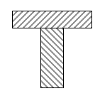
Outside frames were built out of 3"x2" softwood glued-and-screwed, ensuring they remained square until dry. Substantial cross beams and bracing were then installed, also glued-and-screwed, made out of 2" x ¾" timber in a T-shape as per the diagram on the right, with holes pre-drilled in the upright pieces to allow routing for wires. This should ensure a high degree of rigidity to minimise flexing while the layout is being transported and during set up, as it is self-supporting and does not require any extra end-boards or container for transporting. This may seem to be on the heavyweight side but since it was decided from the start that a van would be hired to transport it, and two people would be needed to operate it and therefore be available to set it up, I would rather over-engineer at this stage than deal with damage due to flexing when all the scenics are down! So having built the frames sheets of MDF were firmly screwed in place, making a VERY solid baseboard. Believe me it does not flex! |
 |
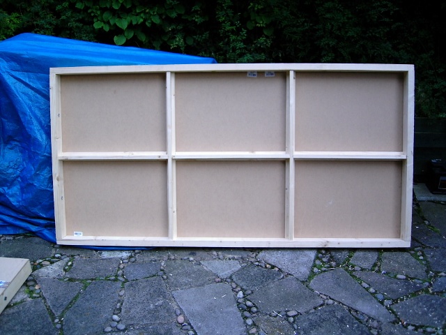
One of the two 6'x3' baseboards done.
|
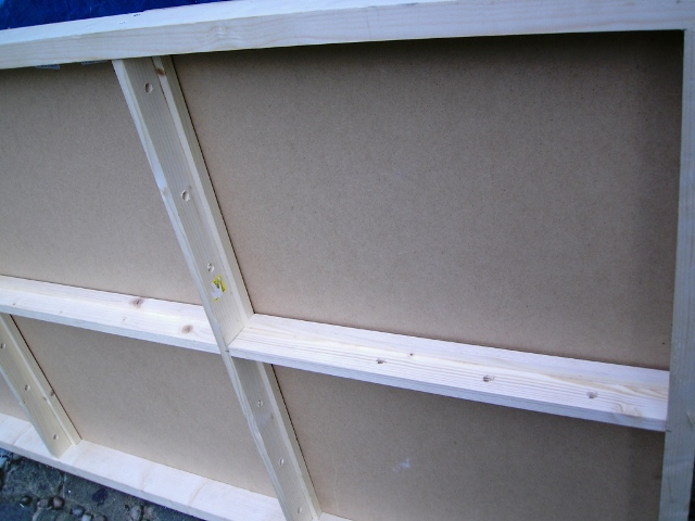
A closer view underneath showing the T-braces and the wiring holes.
|
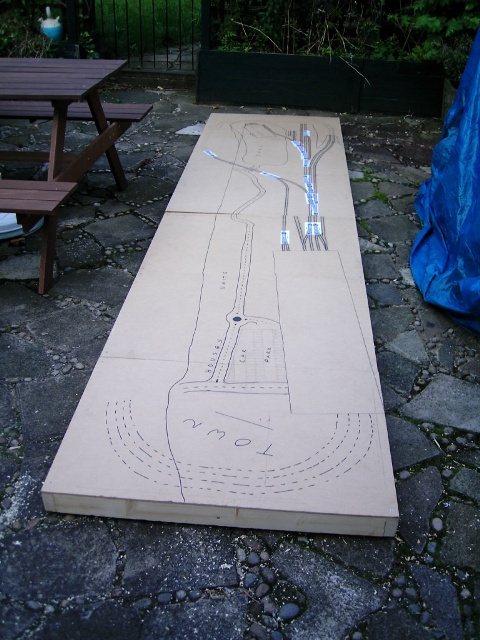
With both boards built attention turned to finalising the track-plan, mostly freehand with a marker and ruler but again using Peco templates for the points. Done in the garden as there is nowhere in the house to have both boards up for any length of time.
Here you can see the early planning of the flat junction for the branch on the far board, now superceded by the over-bridge idea, the beginnings of which are on the nearer board. The large blank rectangle in the foreground on the right is where the cardboard template for the station sits. |
 |
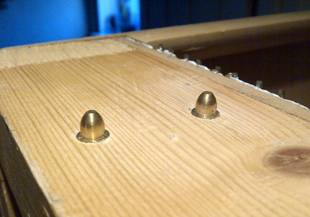
To ensure good alignment between the two boards they were fitted with 8mm Bullet-type Alignment Dowels from Station Road Baseboards. M8 T-Nuts, again from Station Road Baseboards, were fitted into the two 9.5mm holes of one board on the opposite side to the join, and drilled T-Nuts fitted to the other board. Some M8 threaded rod was cut to length to fit through both end-timbers and a wingnut glued on each one with Araldite. The idea when assembling the layout is that the two boards are placed on the modified trestles and slid together so the alignment dowels engage. The two threaded bolts are pushed through the drilled T-Nuts and both end-timbers and screw into the threaded T-Nut on the other side, bringing the two boards tightly together.
Male half of dowels fitted into 7.5mm holes drilled right through
|
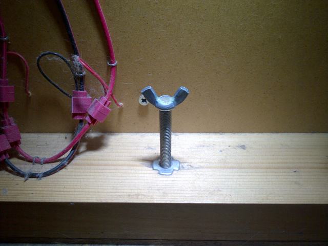
T-Nut fitted to inside of baseboard frame, with home-made securing bolt |
© Sprintex-net 2023 - Go to Sprintexnet home